|
Alternate
Way
to Repair Sagging Mirrors
By Homer
Dawson
First with a
small
screw driver, pop the outer ring of the mirror loose, next remove the
mirror (be very careful not to break the mirror), this will reveal the
10 mm bolt that needs to be tightened, once this is done replace the
mirror, then, with a drop of silicone or glue, re-install the outer
ring back on.
Speedometer
Error
Problem: The
speedometer is in error by a plus 10% (five to six miles per hour at highway speeds.) In other
words, when it reads you are going 60 MPH, you are in reality only
doing 54 MPH.
Solution:
The gear located at the end of the speedometer cable
(on the front wheel) has 25 teeth. If the number is reduced to 23 or 24
teeth, the speedometer will then read close to true. Carl Leo finds that
the 23T gives accurate speeds with a Dunlop Elite 3 tire at 38 lbs psi.
The receiver for the speedo at the front wheel must be replaced
with Kawasaki Part No. 41060-1025 (24t) or 41060-1107 (23t.) You must also put in a new oil seal,
Kawasaki part No. 92049-1057. While you are at it, replace the pinion gear or you are asking
for trouble down the line mixing new gears with old. The part number for the 9t pinion gear is 41060-1016.
An installation tip from Carl: "It is easy to damage the housing trying to disassemble the unit and I see
some that look like kindergarten children worked on them. Be gentle........."
Installation tips from Doug Divine of South Florida: "You have to drill a hole
(same size as roll pin) in the hsg on the opposite end of the roll pin so you can push the
roll pin out. The small hsg that holds the pinion in is pressed in, you need to grip it
good and work it out & it is alum so do not bugger it up to bad. The seal will come out
fairly easy with a screwdriver just pry in different spots, If you are easy with it it can be
reused if need be. I use a marine white lithium waterproof grease, Do not use wheel bearing grease
or a thick heavy grease. Check that the lock or collar with the two big notches that fit in the
wheel are not chewed up, if edges are dinged up you can file them so they are straight, if real
bad you you need to replace and be sure when you put hsg back on that it is set in properly, The
housing where the cable is attached should be almost parallel with the floor. The speedo hsg looks
like it fits between two stantions on the shock but it does not, Look at the way it goes before you
remove it. Cable should go up thru fairing on outside of shock and I always put a small o-ring on
bottom end of cable to keep water out and do not loose little washer on the end of cable and ones on
the pinion. Actually takes longer to type this than to fix it. Like Carl says some are better off just
replacing the whole assy. But I do not think you can get the correct gears that way."
Note that this change will also reduce the odometer reading. I've found the stock odometer reading
to be off only 2-3% instead of the 10% of the speedo. Your observed gas mileage will appear to drop!
Balancer
Gear Backlash
Adjustment
Problem: Many have
complained about Voyager XII gear whine or transmission noise. Although
the Voyager XII has straight cut gears in their transmissions due to
the desire for a more sturdy and reliable transmission, straight cut
gears compared to helical cut gears do make more "gear whine". However,
some time it may be something more than the normal, mostly unobtrusive
straight cut gear whine that you might hear. It could very well be that
the balancer gear backlash needs adjustment.
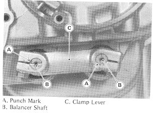
Solution:
A fairly simple adjustment
may be
needed to the balancer gear backlash, here's how to do it (refer to the
picture below):
|
|
You need to look on the right side of
the engine (sitting on the bike) to find the balance shafts clamp
lever- pictured to the left. The punch marks on each shaft should point
to the correct side. The mark on the front shaft points to the rear.
The marks should point in the direction as shown in the photo (to the
rear). Then: |
- Start the engine and let
it at
idle.
- Loosen the balancer shaft
clamp
bolts.
- Turn the front balancer
shaft
clockwise until the balancer gear makes a noise.
|
- Turn back the shaft
counterclockwise until just the gear stops making a noise.
- Adjust the rear balancer
shaft
in the same manner.
- Tighten the balancer shaft
clamp
bolts securely.
|
Keeping
Music Tapes Tight
From
AVA Member Archives
By Ed Cones
After a short while, cassette tapes will "unwind" in the Voyager tape
storage compartment and have to be rewound before you play them or they
could get fowled in the tape player. Ed submitted two methods for
keeping his tapes tight enough to play without having to re-wind them
after storage before playing.
"I've used foam earplugs in my
tapes since I got the bike. They work well, Just roll 'em down like
you're at the shooting range except stick them in the tape."
He also experimented during a long cycle trip and came up with the
following: "If the tape is rewound completely or almost completely,
looking at them from the rear of the bike, the large spool turns
clockwise. So, I rewind my tapes before removing them from the player
and place them in the storage compartment with the full spool down and
the open side of the tape to the right or center of the bike. The
clockwise movement of the large spool keeps them tight. This has worked
great on my bike for 10,000 miles now."
Recall
Notice
Clutch
Back Torque Limiter Warning
Dated November 1999
"Kawasaki Motors Corp., USA has
determined
that a defect which relates to motor vehicle safety exists in 1999 and
2000 model Ninja ZX-7R, Concours, and Voyager XII motorcycles. On
eligible units, the back torque limiter in the clutch may malfunction
and allow the clutch to slip, or not re-engage after a shift. This
sudden non-engagement of the clutch might cause the rider to lose
control of the vehicle, possibly resulting in an accident and personal
injury."
This notice was probably
delivered to all owners for the years and models mentioned above, but
anyone purchasing a used cycle should check to verify that this safety
defect was corrected. Owners previously unaware of the defect should
contact the nearest Kawasaki dealer for further details.
Battery
Sensor
From
the AVA Archives
It seems as though quite a few times the
question has been raised on how to disable the battery sensor on the
VII so the battery light stays out. Some basic observations for the
unknowing should first be considered:
-
The battery
lights purpose is to indicate that the battery electrolyte or water
level is low in the battery. This is handy so you don't need to check
the level so many times during the riding season since it's not the
quickest thing to do.
-
The battery
light
has nothing to do with the quality or life left of the battery, other
than letting you know the water level is low. If the water level in a
battery is left low, it will cause sulfation in the battery cells and
lead to pre-mature battery failure.
-
Most
manufacturers make at least two versions of a battery that will work
for the Voyagers, one with, and one without the battery sensor. Some of
the newest batteries such as the gel batteries, or a maintenance free
battery, prevents you from adding water by design. If you would like
the convenience of the battery sensor and want to use the standard
non-maintenance free batteries, then buy the ones with a sensor. If you
get a maintenance free battery, then you don't need to worry about that
option and will probably just pay a higher price for the battery.
So after you decide which battery you would like to use, and have
decided on a gel, maintenance free, or simply one without a sensor
hookup, then you probably will want to disable the sensor by simply
connecting the sensor lead to a +12 volt source. This can be done by
either using one of the spare leads under the fairing, or simply
connecting it to the +12 volt terminal of your battery. Others have
suggested to hook a 100 ohm resistor in line with the original wire
going to the battery and terminate it at the positive battery terminal.
Changing
the XII Spark Plugs
By
Ed
Cones from AVA Archives
Changing out or cleaning the spark plugs
on
the Voyager XII is not a slam dunk, easy job. It can be made easier,
however, if the battery and battery tray are removed. The Voyager XII
comes with a tool pack that contains a spark plug tool. Using the tool
with an extension and a pair of long needle nose pliers to reach the
plug wire caps makes the job a bit easier.
Please remember to clear the
plug area with air pressure before removing the plugs. Each of the plug
locations will collect bits of stone, dried bugs, and other debris. It
must be cleared in order that the contaminants do not fall into the
spark plug hole when the plugs are removed.
Temperature
Gauge Fix
From
AVA
Archives
It has been reported that several have
had
problems with the Voyager XII water temperature gauge reading either
low or not at all. It has been traced to an inadequate ground. The fix
for this involves checking the grounding for this gauge. You can make a
small ground wire to run from a thermostat housing (which contains the
temperature sender) bolt up to a 6mm bolt in the frame just behind the
steering head, or another good grounding point.
Intermittent
Electrical Problem
(headlight,
gauges, brake and tail)
From the
AVA
Archives
By Denny
Zion
Problem:
Occasional loss of headlight,
fuel
and temperature gauge readings, as well as tachometer, brake and tail
lights. Interruptions usually occur periodically. Loss could become
more numerous as time goes on. Fuses appear or check out OK.
Solution:
More times than not, a problem exists
with the
large connector just after the fuse block. Possibly caused by excess
water or dampness otherwise getting into this connection. The
electrical connection within this connector (plug) becomes corroded to
the point that it makes intermittent contact with it's opposite pin
that powers these items. Disconnect this plug and thoroughly clean all
the pins on both sides of the connector. A good electrical cleaner
should do the trick (such as electrical contact cleaner at a
electronics store, or comparable). After all contacts or pins are
cleaned, a good application of electrical anti-corrosive grease
(usually for aluminum cable- available at electrical contractor stores)
should prevent this from happening again.
Brake
Light Switches
From
the
AVA Archives
By BJ
Reynolds
Problem:
The front or rear brake switch
fails
to activate the brake light when the lever or foot brake is applied.
Solution:
Loose spade connector(s) may
be the
problem. A slight crimping of the connectors should take care of the
problem. It is suggested that you frequently check both the lever and
foot brakes to make sure they are activating the brake lights as they
should.
Clarion
Radio
or CB Service Procedure
Clarion
no
longer services the Voyager XII radios or CB's.
However,
there
are still two outlets where service can still be obtained at this time.
The first outlet we recommend is service and modifications provided by
Peter Franchi. He can be contacted through his email by clicking
here. He can also be contacted through his username
(suzib6sw) on the AVA Message and Information forum here.
The
other
source of service is noted below.
Sierra
Electronics does repair the radios and CB's from Voyagers XII's!
As of
2/17/09, they indicated that they had a 2-week turnaround from date of
receipt of the radio or CB. The typical cost for a repair on
either component is $100. When you send it in, they will go
through it and when they have a firm price, they will contact you for a
credit card to pay for the repairs. If there is anything
excessive, they will let you know BEFORE doing the work.
Their
contact
information is:
Sierra Electronics
2080 Experiment Farm Road, Troy, OH 45373
800-338-6938 / 937-335-8939
Sales@sierra-mc.com
For
more
details on packaging the radio or to confirm turnaround time, contact
them directly.
Easier
Battery Level
Checking
By
Chuck
Tenwick
From AVA
Archives
Problem:
Finding an easier way to check
battery electrolyte level without having to remove battery to see level
lines and associated having to disconnect battery leads etc. to do so.
Solution:
The normal level checking lines which
are on
the front of the battery are not easily read since they face the front
of the motorcycle, therefore, Chuck suggests that the next time you
have your battery out, to draw a line on the back side of the battery
with a magic marker indicating where the full level line is for the
electrolyte solution. This way, a quick look with the dummy tank off is
all that is needed to know where your level is in the battery. He also
mentions that he wads up a small piece of paper to stuff under the nuts
for the terminal bolts. The wads act as springs to hold the nuts in
place when starting the terminal bolts.
Broken
Rear Speaker Mounts- Temporary/Emergency Fix
By Tommy
James
From the AVA
Archives
If the problem is the metal plate separating from the rubber bushing,
place a small drop of super glue type adhesive between the metal plate
and rubber bushing. This fix will work just fine without any problems. Make
sure the metal plate and mating surface of rubber bushing is clean-
even of previously used super glue if broke before, then apply glue and
lower bushing onto it. Weight of speaker should hold it firmly enough
until cured. Allow at least several minutes before riding off to allow
sufficient cure. Also, avoid any oversize packed touring bags placed on
the luggage rack that may tend to spread apart the speakers.- Gary,
Webmaster
Broken
Rear Speaker Mounts- Permanent Fix
Original
Solution
By Bob Hughes
Rewritten and Photos added By Gary Schill and Lori Norris
Using Bob
Hughes' original
article
for fixing broken speaker mounts more permanently, we have expanded the
instructions and included photos. Bob
reports that this repair has proven successful for the last 60,000
miles and 6 years of terrible Michigan roads around the Detroit area.
 |
 |
|
Here
is a problem that plagues many Voyager XII riders, broken speaker
mounts. The rubber part of the mount usually separates from the metal
backing plate and voila, you
have a bouncing speaker. |
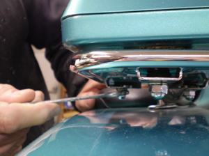
1. To start, remove the speaker mounts from
the speakers and rear luggage rack. There are 3 nuts on each speaker to
remove them from the rack. When
removing two screws each that hold each
of the three rubber speaker mounts, reinsert at least one screw to hold
speaker together. If re-using the broken mounts, first re-glue them
back together to keep them lined up. |
 |
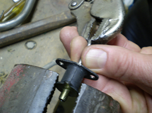 |
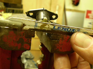
| 2.
Next will be to drill out the
center of the speaker mount stud with a #43 drill bit. These are a wire
gauge drill bit available at better hardware stores. Use
caution when drilling the hole to keep it straight and centered in the
stud as there is not much room for error. |
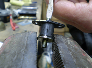
3.
Then it's time to tap out the hole you just drilled in the speaker
mount bolt. Use a tap to thread the hole for a #4 metal screw with a 40
pitch thread. Use oil while tapping out the hole, and be very careful
while tapping so you don't break the tap. Advance a little while
tapping, then back out. Repeat this a few times, then withdraw the tap
and flush the hole with oil and repeat until the hole is completely
threaded. |
 |
 |
|
4.
With the hole now tapped out, use a #4 x 1½"
metal screw. Apply thread locker to thread first, then turn in screw
from the top down until it tightens just slightly so the mount can
still flex some. |
5.
After screw is in and very slightly snug, cut off excess flush with
speaker mount stud. |
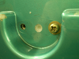 |
6.
You should then drill a small divot in the speaker housing to allow
room for the screw head. We also used one aluminum back-up washer for a
⅛" pop rivet
for
each mounting screw. Be sure all the lock tabs on the speaker mounts
point to the center of the speakers to align with the luggage rack
cutouts. After all the speaker mounts are mounted to the speakers,
remount the speakers to the luggage rack and screw on the nuts removed
in step one above.
| TIP:
When installing nuts especially towards the top trunk hump, it is
easier to start the nuts when the top trunk lid is open. |
|
Another
Alternative Fuel Pump Suggestion
By David Randall
In case you
cannot
get the fuel pump that Jeff talks about above, NAPA
does have an electric fuel pump that will work. It is part number
610-1051, Posi-Flo model. It comes with an add on filter that goes
between tank and pump, and all the fittings, but not any extra fuel
line. You will need a little extra to to locate the Voyager original
fuel filter and to add a little between pump and tank. This pump is set
1.5-4 PSI two wire design, neat and small, will mount on the regular
mounting bracket that the Voyager pump is now on (with just a little
rigging). It also will let you relocate the fuel filter so you can
change it easier. Instead of using the long fuel line adapter that goes
in the outlet end, use an elbow first, then, the adapter. Use the info
Jeff provides about wiring the pump. I used the red hot wire and ground
Jeff talks about, but did not cut the original plug off. Be sure to
mount the back as far as you can on the original mount so the rear
brake reservoir will remount with no trouble. AFter installing the pump
and before putting everything back in place, I checked to make sure
that everything would fit back i place just like factory. Turn the key
on, wait just a minute to let it prime up. Instant start and very
little gas fumes. Down the street and back, using all the throttle I
could, yielded very good throttle response and very smooth running at
last. Total cost for pump and supplies are $60.00 (as of 11/18/07),
much better than the OEM at $175 for a new pump.
Discharging
Battery
By
Gary
Schill
Problem:
The battery seems to discharge
over
about a 2 to 3 week period just sitting in the garage until it won't
start the motorcycle. "It seemed OK when I first parked it, but a few
weeks later, it wouldn't turn the bike over".
Solution:
On the Voyagers, there is a
constant
drain on the battery even when sitting idle, this is because the memory
in the radio, clock, and if so equipped, the CB take a little electric
to maintain their settings. Even if your battery is fully charged when
you park your bike for a extended idle time without riding much, the
battery can easily become discharged enough to not start your machine
in a couple or so weeks. This is normal. This constant discharge and
then charging when you do ride your bike can cause sulfation of the
battery plates, and eventually or prematurely your battery will die. To
best combat this sulfation of the battery plates and keep your machine
ready to ride, you should invest in a "smart" battery charger. The two
most well known brands are the Battery Tender and
the Battery Minder, although there are other brands
manufactured. You can simply hook up the usually provided ring terminal
battery cables to your bikes battery, and when you park your bike for
any amount of time, just plug it in to the battery charger. You can
leave the charger connected indefinitely until you are ready to ride
again, then just disconnect the polarized connector, and you'll have a
fully charged battery ready to go. The charger goes to maintenance or
standby mode until the battery needs a charge to keep in top condition.
This reduces drastically the sulfation problem, and you always have a
fully charged battery ready to ride.
Starter
Chain/Igniter
By
Charlie Sargent
Problem: The starter
chain breaks.
Solution:
This problem was present in
the
Voyager XII model years of '86 and '87. It would usually occur when a
discharged or failing battery was used to start the machine. If you own
an '86 or '87 Voyager XII, it is recommended that you check to be sure
you have the updated igniter to prevent this problem, replacement of
the starter chain with the updated one may or may not be
necessary. Also, keep your battery (all year Voyagers too)
fully charged and in good condition. The following information was
provided by Charlie Sargent who experienced this problem and it's
solution first hand- THANKS SARGE!!
"There have
been
86's/87's that broke the starter chain tensioner and tossed a chunk of
it through the engine cases. A few common traits among all the starter
chain failures are, all were '86/87' models, which had the old starter
chain (p/n 92057-1205). There was an update to a newer chain (p/n
92057-1276), 1986/1987 had the old-style igniter (p/n 21119-1179),
which had problems with over-advancing the ignition timing. The new
style igniter is (p/n 21119-1248) you can check which igniter you have
by removing the tank cover and check the part number on the igniter
box. All machines that experienced failures seemed to have had low
batteries that cranked the machine over slowly sometimes and then turn
over normal other times. (It put a lot of stress on the starter chain
until it failed.)"
Installing
Progressive Fork Springs
By
Gary
Schill
OK, you've decided your
front
fork
springs are sacked out, or would like the best performance and ride of
the Progressive springs. You might think all you have to do is take the
old OEM's out and replace with the Progressive's, but there is a
difference in the springs that will require you to change the
re-assembly process. The process of changing springs (as well as fork
oil) is not all that hard, but is more difficult than changing either
one on some other bikes. So here's the process:
The fork springs you
need are Progressive Part No. 11-1102 for '87 thru '03, (1986
Voyager XII's use
Progressive Part No. 11-1122), these are Progressive's numbers, it may
be listed under a different part number depending on the dealer or
distributors numbering system- check their listing for the Voyager XII.
This spring ( Part No. 11-1102) also fits several other machines (some
will require a spacer to adapt). Following is the machines that also
take this spring:
|
Make
|
Model
|
Years
|
| Kawasaki |
ZG1200
Voyager |
1987-2003
* |
| Kawasaki |
1300
Voyager |
1983-1987 |
| Kawasaki |
ZG1000
Concours |
1986-2002 |
| Kawasaki |
GTR1000 |
1986-1996 |
| Honda |
700
Interceptor |
1984-1985 |
| Honda |
750
Interceptor |
1983 |
| Honda |
CB1000C |
1983 |
| Honda |
CB1100F |
1983 |
| Honda |
CB1100R |
1982-1984 |
| Honda |
CB900F |
1980-1982 |
| Honda |
GL1100
Gold Wing |
1980-1983 |
* Note:
1986 Voyager XII's
use different Progressive Springs since the stanchion tube
diameter was different in the first year of Voyager XII production.
Process of
spring
installation:
-
Remove
front
brake calipers, speedometer cable from front wheel receiver.
-
Release all
air
from front suspension.
-
Remove
front
wheel, fork brace, and front fender.
-
Loosen top
triple
clamp bolt on one of the forks.
-
Completely
remove
the lowest bolt on the bottom triple clamp on the same fork with a
wrench (box or open end).
-
Loosen the
top
bolt of the bottom triple clamp.
-
While
holding the
connecting pipe collar up, rotate the fork tube and begin lowering it
in the triple clamps. (See photo 1)
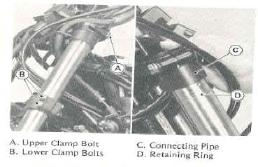
Photo 1
-
Before you
can
remove the fork tube completely from the bottom triple clamp, you must
first remove the retaining ring ( D in the photo), on the fork tube
upper. This retaining ring will become visible after you lower the fork
tube from the top triple clamp. You can remove it by using a slot
screwdriver or other tool to expand the ring and lift it off the top of
the upper fork tube- be careful you do not bend it.
-
After you
remove
this retaining ring, remove the fork tube from the motorcycle.
-
Remove the
top
black plastic fork tube cap.
-
Now the
tricky
part, it's best to have a vise and a friend to help you with this one,
but can be done by yourself with a little patience, muscle, (and maybe
some colorful "french").
-
Wrap a rag
for
good cushioning around the upper fork tube 3 or 4 inches from the top,
or better yet, use about a 3 or 4 inch wide strip from an old rubber
inner tube and long enough to make about 3 wraps around the fork upper
tube, and carefully place it in the vise, only tighten the vise enough
to securely hold the fork tube from slipping down when pressure is
applied to the top plug of the fork tube, not so much as to even begin
to collapse the fork tube ( make sure there enough cushioning to
prevent any marking on the fork tube and do not over tighten the vise).
Test to make sure the fork tube will not slip.
-
Then by
yourself,
or with a friend's help, press down on the top plug of the fork tube,
and, then remove the retaining ring to allow the top plug to come out
of the fork tube. (See photo below) Be careful to gradually release the
downward pressure as the top plug will have spring pressure on it.
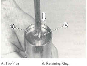
Photo 2
-
Remove top
plug,
oil filter, collar, and fork spring.
-
Remove fork
assy.
from the vise, remove the bottom drain plug on the fork assy. lower,
and drain the fork oil by pumping the fork tube several times until oil
is all out. (Observation: what color is the fork oil? Does it look like
well used (black) engine oil? If so, you waited too long to change the
fork oil!)
-
It is
suggested
that you clean out the fork internals before installing new oil. I did
this by using clean paint thinner and continually flushing it until it
came out clear (put some in, pump the fork several times, drain-
repeat). Do not use gasoline, lacquer thinner, or other strong solvent
(example: auto paint thinners).
-
When you
are
convinced that you have the fork internals clean, then you are ready
for reassembly, make sure you have all of the paint thinner or
equivalent drained from the fork.
-
Fully
compress
the fork and support it so it stands up straight. Before you install
the new fork springs, you must add the required amount of oil. As
mentioned under the tech tip "Front Fork Oil", the best way to bring
the oil up to the required level for the Voyager is to measure from the
top edge of the fork inner tube to the top of the oil level (it should
measure 145mm for Progressive Springs, 140 for stock OEM springs). Use
some kind of measuring tool or improvise to accomplish this, I used a
heavy plastic zip tie, and put a piece of tape 145 mm from the tip of
the tie. I lowered the straight zip tie into the fork inner tube till
the tape lightly touched the fork tube. I then added oil till the fork
oil just showed on the zip tie. Note: Progressive recommends 160mm ± 2mm of oil level. Carl Leo has determined
that 145mm air gap works best for Progressive springs in the Voyager XII
(1200). I had originally used the 160mm air gap level, and found that it
was not enough oil. Use the 145mm air gap measurement .
-
Now,
reinstall
the fork assy. into the vise again like before, install the new
Progressive springs. Now for the difference between the stock fork
springs and the Progressives'. On the Voyager XII's, you DO
NOT reinstall the collar or oil filter like it was when using
the OEM springs. The Progressive springs are longer than OEMs and do
not require these parts. All you'll be installing is the new fork
springs followed by the top plug, then the retaining ring.
-
Now with an
assistant's help (preferred), or if doing by yourself, you need to
reinstall the top plug, hold the top plug down as before and reinstall
the retaining clip.
-
Now
reinstall the
fork assy. back onto the motorcycle. After you get it through the
bottom triple clamp, reinstall the retaining ring back onto the inner
fork tube, See photo 1.
-
Next, by
slightly
rotating the inner fork tube back and forth, guide it back up through
the Connecting pipe (air equalizing collar) and then up into the upper
triple clamp. Tighten all triple clamp bolts. Reinstall black plastic
fork tube caps.
-
Complete
steps 4
thru 22 for the other fork assy.
-
Then
reinstall
the front fender, fork brace, front tire, speedometer cable, and brake
calipers.
-
Your Done
and
ready to ride!!
Water Leak
By
John
Stone MTSV
Problem:
Water leak on the Voyager XII
while
in winter storage. This clears up once the riding season starts. The
leak comes from one side of the horizontal pipe in front of engine
(like a manifold) with two steel lines running into it coupled by a
small length of hose with hose fittings on them. There are two possible
answers:
Solution:
1. Dealer suggests endure the first few
leaky
experiences into spring and ride it the rest of the summer once the
leaks stop. Alternative is to replace seals that dry out in winter,
costs about $100.00.
2. This comes from Alex
Mistal
in Redding CA: Same problem but his leak came from loose hose clamps.
Most of the hose clamps can be tightened without removing any plastic,
but the ones on the top can only be reached if you remove the false
tank, battery, and battery case. Still a job that the average biker
should be able to accomplish without too much difficulty.
Protecting
Fork
Seals
By Chuck
Hoefflin
I
had some difficulty with the fork
seals on
one of my BMW's due to hardened bugs that were stuck on the fork tubes
and damaged the fork seals. I found a Yamaha sport bike that had a
plastic protector that I could adapt. I used that arrangement for the
rest of the time I owned the bike. When I bought my Voyager, the same
problem exists. The fork tube is exposed. So I modified fork protectors
from a Yamaha 4TX-2331G-00 to do the job. For reference, they are 3
5/8" high, plenty to protect the exposed surface of the fork tubes. I
had to modify them for clearance around the stock fork brace- a five
minute job. Cost: less than $5 per side.
|


