|
Rear Tire Change
By Mike
Rallis
1. Put bike
on
center stand.
2. Disconnect wiring connectors then remove saddlebags.
3. Remove two bolts for the exhaust for each side. Bolts are under the
rear floorboards and aft.
4. Loosen the bolts to the exhaust just forward of the crossover tube
for the mufflers. One on each side.
5. Remove two bolts from rear crash bars that hold the attachment for
the saddlebag mounts.
6. Remove three bolts on each side of the rear fender flange.
7. Remove the rear fender flange. Disconnect the two wires at the top
under the trunk. This disconnects the license plate light.
8. Lower the exhaust pipes just enough to clear the axle bolt.
9. If you have a Markland trailer hitch, remove it. This will help with
the tire removal.
10. Remove the axle cotter pin and nut.
11. Remove the axle and the brake bolt on the swing arm.
12. Remove the rear brake housing and make sure that the housing isn't
hanging by the brake line.
13. Pull the wheel off the hub towards the right side about two inches.
Be sure that you have a firm grip on the wheel, otherwise something
like hands and/or fingers can get pinched.
14. Pull the wheel out the back end of the bike.
To re-install
the
new tire and wheel:
15. Coat the
shaft
splines with light grease and reattach the wheel back on the hub.
16. Reverse the order above to reinstall.
17. Tighten the rear axle nut to 80 ft/lbs. of torque and the brake
caliper bolt to 72 ft/lbs.
Your ready to
ride!!
Sticking
or Dragging
Brakes
(Will
work for
Front or Rear Brakes)
By Gary Schill
Problem:
You are noticing that your brakes,
either
front or rear, are starting to drag and/or what could be called
moaning. It could also be felt as a minor but noticeable vibration
while the moaning is taking place. It may or may not emit a squeal,
which more likely may be a out-of-service limit brake pad, but if your
brake pads are within service limits and you still hear a squeal or one
of the before mentioned symptoms, or you feel your pads are prematurely
wearing out, then read on.
Solution: The problem may be either a
sticking caliper piston, or dry caliper holder shafts and holder holes.
Refer to the diagram below (although it shows the rear brake set-up,
this will work for both front and rear brake).
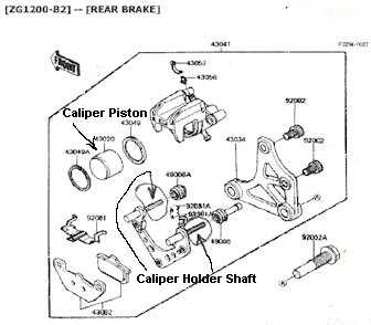
More than likely, the problem will be dry caliper holder shafts and
holder holes. The caliper holder shafts should slide back and forth
fairly freely in the holder holes, however sometimes these parts which
should be operating in grease, tend to dry out after while and should
be checked at least whenever the brake pads are replaced. First, clean
these shafts and shaft holes using isopropyl alcohol, or ethyl alcohol,
or even disc brake fluid. Do not use gasoline, motor oil, or any other
petroleum distillate, as this will cause deterioration of the rubber
parts. When lubricating these shafts, Kawasaki recommends using a Poly
Butyl Cuprysil grease (PBC is a special high temperature, water
resistant grease). I have used heatproof plumber's grease which is
supposed to be a high temperature silicone base grease, which has
worked well for me so far. After cleaning and greasing the caliper
holder shafts and holder holes, reassemble the brakes and try them
out.
If you notice that your
hydraulic brake fluid is the color of root beer or something similar
(should be mostly clear to very slightly amber) and it has been this
way for some time, your caliper piston MAY be sticking, change and
flush your hydraulic fluids (you should do this at least every two
years, brake and clutch). If you still experience sticking brakes, then
you may need to examine and clean the caliper piston and probably
replace the caliper piston seal and dust cover, also check the master
cylinders as these could also be possibly sticking due to excess
moisture in the brake fluid (that's what turns the fluid the root beer
color.)
Voyager
XII Air
Filter Alternative
By
Bill Bunn
A STP SA3915
replacement
air filter will fit perfectly into the Voyager OEM white plastic basket
by trimming approximately 1/8" off two opposite ends with a razor
cutter. Apply silicon or other sealant in the bottom of the
basket and place the wire side of the new filter down into the
sealant. Don't forget to the reinstall white plastic ladder
looking holders. The cost at our local Advanced Auto Parts
was under $5. A NAPA 6140 or WIX 46140 will also fit with
appropriate trimming.
To get the maximum safe use out of your tires and
maximum touring enjoyment you should:
- Properly maintain all aspects of your
vehicle in accordance with manufacturer's recommendations. Read and
reread your motorcycle owner's manual.
- Never exceed the loading and
accessories
restrictions found in your motorcycle owner's manual, or the maximum
load displayed on the tire sidewalls. Know your loaded vehicle weight!
- Check air pressure at frequent,
regular
intervals, particularly just before and during long trips. Always use
an accurate tire gauge* and check pressures only when the tires are
cold (i.e., wait one hour after running). We have found many cheap
gauges to be off more than 5 psi, so be sure to use a top quality gauge
and preferably one that retains the pressure reading until reset!
- Inspect your tires as often as
possible.
Look for irregular wear, any signs of cracking in the sidewalls and
tread, blisters, knots, cuts or punctures. Immediately remove and
replace damaged tires.
If in doubt, ask your motorcycle tire dealer to
check
your loading, inflation and tires. Remember, your tires stand between
you and a serious accident.
For touring motorcycle loading, follow these general guidelines:
A. Light loads-single rider with some luggage (up to 200 lb.
total)-minimum tire pressure of 32 psi front and 36 psi rear must be
maintained.
B. Heavier loads-dual riding and/or luggage (from
200 lb. total up to maximum motorcycle capacity stated in the owner's
manual)-pressure of 36 psi front and 40 psi rear must be maintained.
Please Note: For any dual riding or fully loaded use, 40 psi must be
maintained in all Dunlop rear tires fitted to touring
motorcycles. In addition to following these recommendations,
notice what your tires are telling you while you're riding. If your
steering response is slow or mushy, or if cornering and braking
response is heavy, there's a good chance your tires are under-inflated.
Vibration or wobble may signal that actual tire damage has occurred and
failure is imminent!
Reprinted
with permission from DunlopTires.com
Installing
Rivco Air Horns
By Rick Jarosch
I
ordered the Rivco Air Horns to "Be Safe and to Be
Heard." The box includes Triple Chrome Plated Air
Horns, mounting hardware, hoses, relay, fuse and very good picture
instructions. It took about one hour to install.
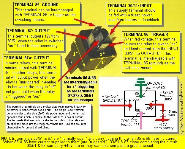
1.
Remove right side lower fairing. Remove 2 bolts holding in stock horn.
2.
Disconnect 2 wires from stock horn and attach them to relay.
The air compressor draws too many amps, and would short out
the horn thumb switch. Run power to relay from
battery with the included wire and fuse, and
attach a ground to other terminal of relay.
3.
Attach mounting bar using 2 old horn bolts.
4.
Use screw clamp, mount air compressor to frame. Keep hoses and wires
away from exhaust.
5.
Put right lower fairing cover back on bike. Use a little water or
saliva, and connect air hoses.
6.
Screw in single mounting bolt. Use thread adhesive to prevent movement.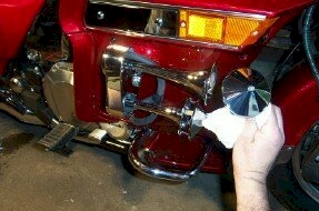
7.
Attach cover with philip's screw.
Test
horn. At 128-decibels, it is about 4 times louder then the stock horn.
If
the wife complains: Are you spending money on that thing again? You
won't be lying this time when you say "But honey, its for safety"!
Minor
gripe: the installed Air Horn was noticeably pointed to the
right of the bike. I disassembled everything up to step 4 above. I used
2 18" pipe wrenches and moved the mounting bar forward about 1 inch.
After reinstalling everything, the Air Horn now faced straight ahead.
Here
is Rivco's web address:
https://www.rivcoproducts.com/
How
to Use the Voyager
XII
Center Stand
By Gary Schill
Here seems to be a hot topic, especially among Voyager XII owners that
bought their bike used and it came without an owners manual. The
Voyager XII center stand is among the easiest center stands to hoist
the bike up onto- if you know how to do it, and that is not hard. There
are several suggestions that I've seen given on how best to use this
stand, from facing the back of the bike and lifting with the left foot,
to putting a board under the rear tire and then trying, and a few
others. However, most of these appear to be procedures to overcome a
problem that otherwise should not exist. So, before going any further,
I would like to suggest things to do or check that will make using the
center stand easy and effortless.
-
Make sure you
have the
rear suspension air pressure within a reasonable or recommended range,
most times between 35lbs. for solo riders, and about 40 lbs. for two up
using the stock Voyager rear shocks. Your front suspension should also
be within service limits for pressure, about 5-15 for stock (although
at the upper range of this, your front fork springs are more than
likely sacked out and need replaced- use Progressive Springs), if you
have Progressive's, 0 to 10 lbs. should do it. With pressures below
these settings, your bike will set lower and make using the center
stand more difficult than it should be.
-
Tire air pressure
within recommended range. Dunlop recommends 36lbs. front and 40 lbs.
rear for most of their touring tires.
-
Your center stand
is
not missing any parts or broken. This may sound a little odd to
mention, but especially when buying a used Voyager, some of the parts,
especially the 1st stage lever, may be missing because of improper use
of the center stand by someone, which led to 1st stage lever breakage,
and it was never repaired or replaced.
-
Choose a LEVEL or
SLIGHTLY uphill area with a fairly hard surface ( cement, blacktop,
etc.) in which to hoist your Voyager up onto the center stand. Downhill
attempts will be difficult if not almost impossible, you may also put
excessive pressure on the 1st stage lever, possibly breaking it (that's
why some used Voyagers are missing this lever), and your bike will have
a tendency to fall forward off the center stand. If the bike sits on
too much of an uphill grade, you'll have a very difficult time getting
it off.
-
Make sure your
transmission is in neutral.
Here we go:
|
|
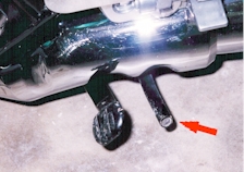
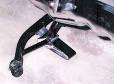
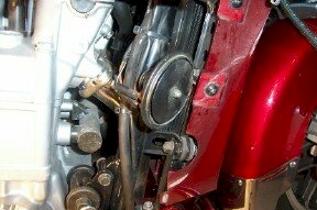
1. This is what your center stand
should look like peeking out from under your stock mufflers on the left
hand (as sitting on the bike) side of your Voyager. The tubular "pipe"
is the 1st stage part of the center stand (red arrow pointing to it),
if this part is missing, you should make arrangements to get the broken
part re-welded on if you have it, or fabricate one to take it's place.
The larger part with the foot pad on it, is the 2nd and main stage of
the center stand. |
|
|
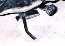
2. With the machine on level or very
slightly uphill surface, hold the bike upright while standing on the
left side, front wheel pointed straight ahead. Have your left hand on
the left handlebar grip and your right hand on the rear passenger
chromed grab handle. Put your right foot on the 1st stage lever and
gently lower into position until the center stand "feet" are resting on
the surface and the bike feels "centered" on them. You may have to pull
the bike slightly rearward while doing this, and you want both center
stand feet on the surface and fully forward. |
|
|
3. Now place your right foot on the 2nd
and main stage of the center stand (the one with the larger foot pad on
it), and just use a moderate down pressure on it. If you are doing this
on level or slight uphill surface- hard surface, (it can be done in
gravel, but will need to be more delicately done), the bike should
fairly easily pop right up on the center stand. If not, review the
steps here and make sure your stand is mechanically and physically
sound. With very little practice, you should be a pro in no time!
|
Voyager
XII Oil
Drain Plugs
Locations
By Gary Schill
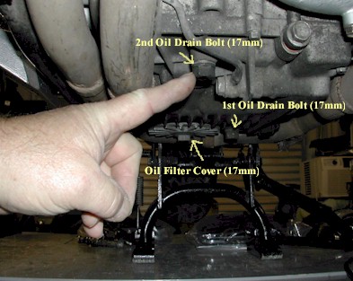
Most motorcycles when draining the oil, you remove one drain plug and
possibly remove the oil filter to remove most of the oil from the
engine and transmission. However, with the Voyager XII, things are just
a little more complicated. With the Voyager XII, you need to remove TWO
drain plugs (17mm bolts) and the oil filter (which also has a 17mm bolt
in the middle of it to remove) to completely drain the oil. As usual
with any engine, it is best to warm the engine first to facilitate
easier and more complete draining. Have the engine warm, not hot, and
make sure the exhaust pipes are not hot when draining the oil so to
lessen the chance of burning yourself in case you come in contact with
the exhaust pipes or spill some oil on you when you first remove the
drain plugs. If you do not remove both drain plugs and the oil filter,
you will not have all the old oil out. See picture below that was
submitted by Fritz previously on the AVA message forum for location of
both drain plugs and the oil filter cover. Fritz is pointing to the
second drain plug that is missed by many unfamiliar with this Voyager
peculiarity. Do not remove any non-17mm bolts as they are for other
things, the bolt next to the 2nd oil drain bolt for example is for
engine oil to pass through. The bolt barely visible in the upper right
hand corner is one of the engine coolant drain bolts.
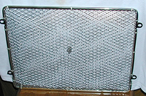
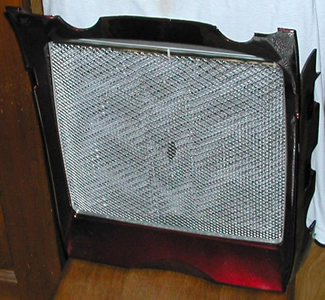
Radiator Grille Dress-Up
By "Wild Bill" Chandley
I discovered some anodized
aluminum mesh
grille material in the J.C. Whitney catalog for $19.99. It's
available in Red, Blue, Black, and Silver... and comes in either a
Small or Large diamond pattern. It's intended for automotive
use, like a decorative insert behind the grille opening of a car or
truck... but I noticed the size was large enough to fit the radiator
grille of my Voyager XII (with substantial material left
over) and figured it might be suitable for use as a decorative
covering.
So I ordered some
in Silver, and it
arrived yesterday. I wasted no time in fabricating my new
radiator mesh grille as follows:
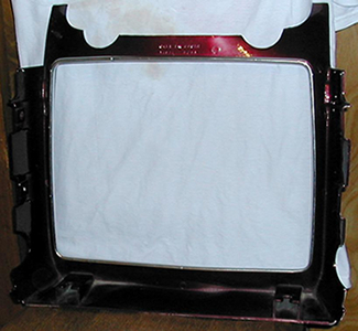
(1) I began by installing some plastic chrome edging around
the black-painted perimeter of the OEM grille. After
cutting a piece of the new mesh to the size of the OEM grille, I
realized I'd have to take off the edging
again (in order to fit the outer lip of the new mesh
under it) and reinstall it. That's what prompted me to use
the wire ties --- because the adhesive inside the chrome edging is only
intended for a single use, and I was afraid it wouldn't stay
put. I gave some thought to putting more (new) chrome edging
on, but since the wire ties are hidden by the outer radiator
cowling anyway, I'll probably just leave them as is.
 |
 |
|
(2) I'd previously
installed the same plastic chrome edging on the inner lip of my
radiator cowling (rear view).
|
(4) Here's the
radiator grille (with new mesh installed) just sitting in the opening
of the cowling (not centered vertically). |
Anyway... I think it turned
out pretty well as a $20 alternative to having the
OEM grille chrome-plated. (Now I'm gonna see what I can do
with fabricating some mesh inserts for my side cowlings out of
the same material).
P.S. - If I do any more of
these, I'll
definitely cut out the mesh grille BEFORE putting on the plastic chrome
edging. Also, the diamond openings in the new mesh are
smaller than the OEM openings... there was a Large Diamond mesh listed
by J.C. Whitney, but since no measurements were given, I was afraid the
openings might be too
big. (Actually, the small openings may work out
better, as far as keeping bugs and debris out of the radiator...).
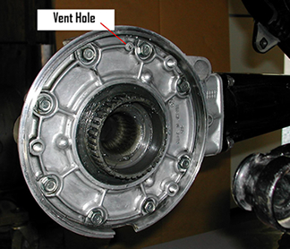 |
Voyager XII's mostly came
stock
with a vent hole in the final drive, later, some thought it was better
to plug this hole to curb oil leakage from this area. However, it was
later found that higher than normal (anything above ¼" below final drive fill hole)
contributed to most if not all the oil leakage, and plugging the final
drive vent hole actually could increase oil leakage because of pressure
build up as final drive oil heated up and forcing oil past the seals,
therefore, it was recommended to re-open the hole if previously plugged.
Here is a picture of final drive vent location. 1/16th
inch hole is good. Just enough to vent the drive. Make sure you cover
up the gear to keep metal chips out. I used a shop vac and hold it next
to the drill bit while drilling. Sucks up all the metal bits. |
For
instructions to
re-open this final drive vent hole, see below:
Drilling
a final drive
After you
remove the
rear wheel, cover the final drive gear with a rag so you don't
get chips of metal
on it. Myself, I use masking tape to tape a rage to
the final drive face to make SURE no chip get on the gear. A
little note... look at the amount of grease on the gear. Don't
use anymore than that amount. I've seen too many mechanics
putting WAY TOO much grease on that gear. It doesn't take much
grease to work. If you use too much grease, when the final drive builds
up heat, this grease will turn to an oil and
will be thrown outward against the inside of the hub and leak
out onto the wheel and tire. Oil on tires are not a lot of
fun. :O)
Use a 1/16th
drill
bit. measure back from the tip of the drill bit about 3/16th
to 1/4 inch and wrap a piece of electrical tape around that
point. This is to give you a guide as to how far to drill into
the final drive case. Its just so you don't drill through
the
outside of the case. The bit will go in more than that but
its a good reminder to not drill too far. NOTE: I use a
shop
vac and hold the hose up to the drill bit while I'm drilling.
Most of the time it will suck up all the chips and none will
even fall on the rag. No matal chips should go into
the final drive case
because it the nature of the drill bit to pull metal out away from
the hole. You can use a small piece of wire to poke in the
hole to make sure it was drilled all the way through. Even in
the worst case scenario that a small chip would get into
the final drive,
it would only get eaten up in the gears. You should have
no problems as long as you pay attention.
Alternator
Rubber
Dampener Location and Inspection
By Fritz Wells (The Masked
Rider)
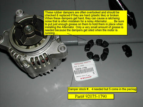 |
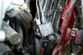
Here
are some pictures
showing the rubber dampeners that help keep the Alt noise down. These
rubber dampeners should be med soft rubber. If they are hard like
plastic, they should be replaced. Noise coming from the Alt. area does
not always mean the Alt is the problem. Hard dampeners can make a lot
of noise.
|
|
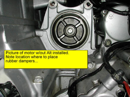
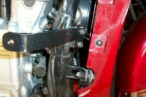
View
of
where the alternator is mounted on a Voyager XII. Removing or
installing a rebuilt alternator is not a hard job, they are fairly easy
to get at and are straight forward in removal and installation. Note
that the stock alternators are 35 amp output and the only parts
available from a dealer is the alternator brushes. If your alternator
is unable to be rebuilt for some reason, check out the alternatives on
the AVA's Dollar4Dollar page. |
|
Carburetor Drain
Screw and Idle Jet Adjustment Locations
By Fritz Wells (The Masked Rider)
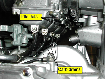 |
Here
is
another excellent picture from Fritz. It shows the locations for the
carb drain screws (to drain carburetor float bowls- Voyager XII), and
where the idle jet adjustment screws are. It must be noted that the
idle jet adjustment screws are hidden by soft plugs to prevent
unauthorized adjustments from factory settings to satisfy pollution
requirements.
|
Fuel
Pump Point Access
Pics By Fritz Wells (The Masked Rider)
Text by Gary Schill
When you might think that your fuel pump has bought the farm, it is
probably a 90% chance that the only problem is just dirty or pitted
fuel pump points. When the points don't make good contact, the pump
doesn't work, and your bike will not start or may not run properly if
it does. The Voyager fuel pumps (Voyager XII's), use a point system
which may become corroded, much the same way distributor points used to
do on cars. If the points become corroded, or do not make good contact,
they will need cleaned. Kawasaki has tried to solve the problem of
corroded points by sealing the points on 1990 and later model bikes. If
your bike is pre-1990, it will be easier to service the pump, as they
are not sealed. This article will show you how to get to the points if
it is 1990 or later, but the location and construction of the pumps are
the same. Although some have adapted other type fuel pumps to the
Voyager, it must be noted that the Voyager pumps are a four wire pump
and not the two wire pump as some are. The OEM Voyager pump has some
safety features on it that will only work when all four wires are used.
Two wire pumps can be used for emergency or even more long term use,
but they will not have some of the safety features that the OEM will.
So, you feel your pump isn't
working. Look at the following
pictures to see how to disassemble the pump and general features and
locations of the pump and connections.
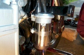
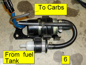 Although
Fritz had intended this to be one of the final steps to pump point
cleaning, to show the routing, I used it here to show what the pump
actually looks like along with the fuel filter which is mounted below
it. To find the pump, one must look on the right side of the bike, just
above and behind the rear wheel brake fluid reservoir. After you
complete the point cleaning or reconditioning, refer back to this
picture for routing of the hoses from the fuel tank and to the
carburetors.
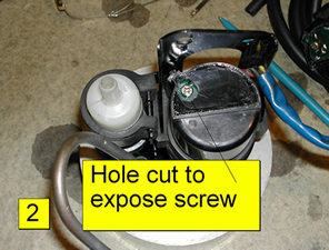
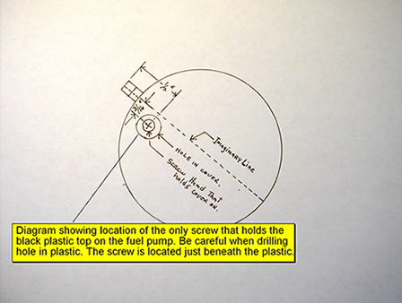 As
noted in the yellow
box on the diagram to the right, this shows where the screw is located
that holds the pump cover onto the pump. This screw may be more easily
seen in pumps that came as original equipment on Voyager XII's from
1986 to 1989, but after that were sealed. Use this diagram to plot
where to drill a very shallow hole to access this screw (the only one
holding the pump cover on). Only drill just through the plastic cover
as the screw is directly below it.
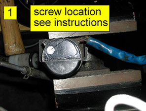 With
the fuel pump removed from
the motorcycle and placed in a vise, use the diagram above to mark
where to drill a shallow hole to access the fuel pump cover mounting
screw. That location is shown in white here. This is where you will
drill a shallow hole or otherwise remove a little plastic from the fuel
pump cover to access the pump cover mounting screw.
 |
 |
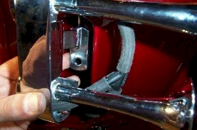
| Here is shown the hole that was
drilled or otherwise plastic was removed to expose the pump cover
mounting screw. |
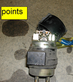
And here are those little bugger
of a points that cause most of the problems (when and if a problem
occurs) with the XII fuel pump. Inspect the points, clean and dress as
required. If the points are pitted,
file them smooth. A good electrical cleaner such as found
at Radio Shack® or other electronics
stores is best to use. After cleaning, you may want to give the points
a light coating of WD40, LPS1 or similar waterproofer. |
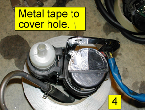
After
you have the cover reinstalled and the cover mounting screw tightened
up, cover the hole you made to expose the cover mounting screw with
metal tape to reseal it. Remount the fuel pump and filter assembly back
on the bike being careful to properly hook up the hoses as shown in the
first picture of this article (noted as #6). If it has been some time
since you replaced your fuel filter, now would be a good time to do
that since your right there. There are a few alternative fuel filters
for the Voyager XII's listed on the
Dollar4Dollar
(new window) page if you don't want to use or cannot get an OEM fuel
filter. After all is back together, enjoy the ride!
Brake Sponginess
As
related to Mike McGee from
Kawasaki
Technical Rep. Brian Fugate
Before I left on a trip from Florida, I topped off the rear brake
master cylinder. Then I forgot to put the cap back on for a
whole day (South
Florida
humidity). Knowing it was contaminated by moisture, I pumped
out the whole system, and refilled with DOT 4. When I pumped
and bled the brake system to get out the air, I could not get any pedal
pressure. I bled the brakes 20 times. No
pedal. I rode to Americade with no usable rear brake and
didn't have time to go to a dealer to have it checked. When I
stopped second night in Pennsylvania,
I bled it 30 more times. No help. When I got up to
Americade, I spoke to
Kawasaki's
Technical Representative, Brian Fugate. He took the time to
listen to the problem and the story. We opened the rear
master cylinder reservoir cap and tried it a few times. No
luck. Finally, after much thought, he told me to hold the
pedal down, left the nipple open and did this: He grabbed
both sides of the rear brake caliper and squeezed them
together. Out popped a large bubble of air that was trapped
in the caliper. He closed it and on the next pump and bleed,
the rear pedal was hard as a rock. I had read the owner's and
service manual. No mention was made of this. I
never heard anyone ever talk of this before. It was a
revelation. If you have the same problem, try this technique.
CB/Radio Display
Not
Working Correctly
The channel display on the CB controller no
longer
works
correctly, and the unit may quit transmitting. There is a
click when the push-to-talk button is depressed but the TX does not
light up. It does receive however and change channels but with no
display, it is not possible to know what channel the unit is on. The
back lighting on the unit also works.
This problem
is more
common than you might think. One method of correction that works for
many, is to disconnect the hot lead on the battery for about a minute,
then reconnect it. This will reset the controllers and most likely will
fix your problem. If that doesn't work, you may then want to check the
connections on the back of the CB display for any loose, disconnected,
or corroded connections.
|

